|
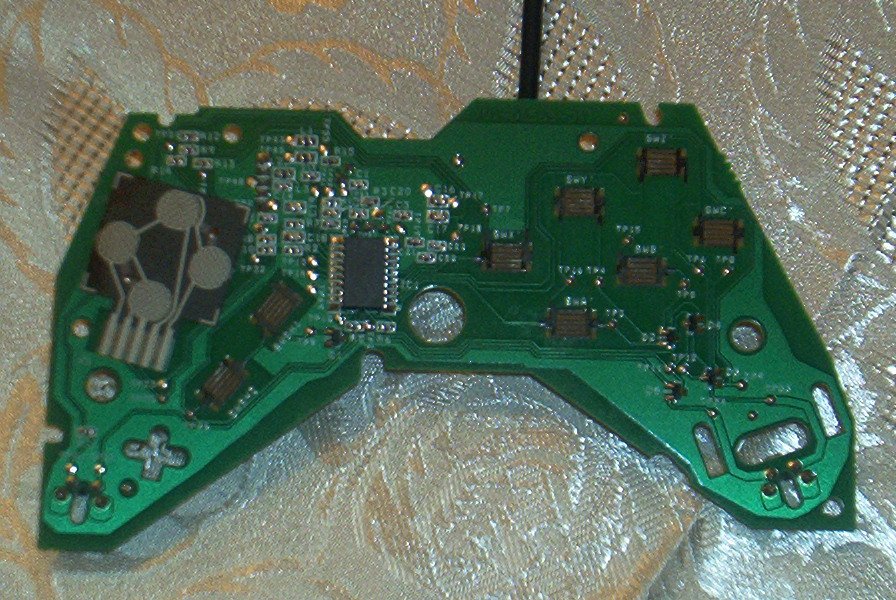
If you havent figured out how to take your gamepad apart then you probably wont want to continue with this project. If you can tear it apart and soder a little then everythings a go and we've got some things to talk about. Once you have to pad torn apart you will see something like this.
| Sidewinder Pro USB PCB |
|
| Click for larger image! |
What you are looking at is the gamepad's PCB. I looked in every nook and cranny of this mess we call the internet and failed to find a schematic of it anywhere. So what did I do. I made one,lol. The image below is labeled with the circuit points I will be referring to in this article.
| Labeled PCB |
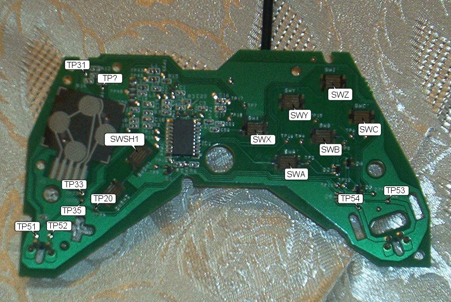
|
| Click for larger image! |
Unlike the original Sidewinder I havent the foggiest idea where the common ground is that will work for the entire board. How do we fix this? Not to worry I have detailed pictures showing you what to do where. The left side of the PCB houses the D-PAD and buttons 7 & 9. Below you will see a labeled picture of the left side. Warning!!! BEFORE YOU SODER ANYTHING TOUCH THE WIRES TO THE BOARD AND MAKE SURE YOU HAVE CONTACT!!! This can be confirmed using the sidewinder test program.
| Labeled D-Pad |
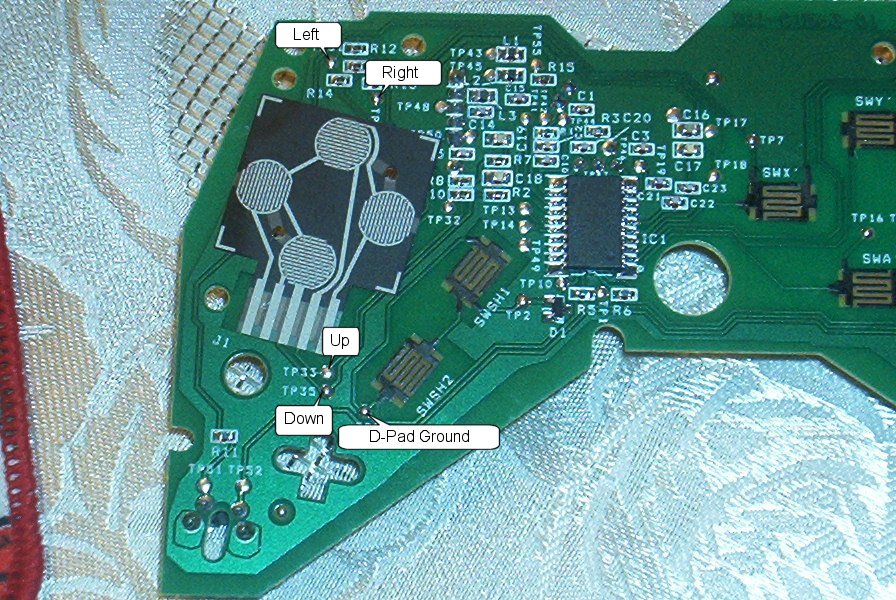
|
| Click for lager image! |
Now that you know what spots on the PCB do what you are ready to wire the D-Pad. Using the ground for the D-Pad. Connect a long piece of wire to it....this will be the ground for the entire D-pad. Hook this wire to the ground on each prong on the joystick. Attach another wire at each point specified on the PCB to the coordinating positions on the joystick. This will give you directional controls. Sweet :) Half-way there....
The next pictures are the wiring diagrams for buttons 7,8, and 9.
| Button 7 Wiring |
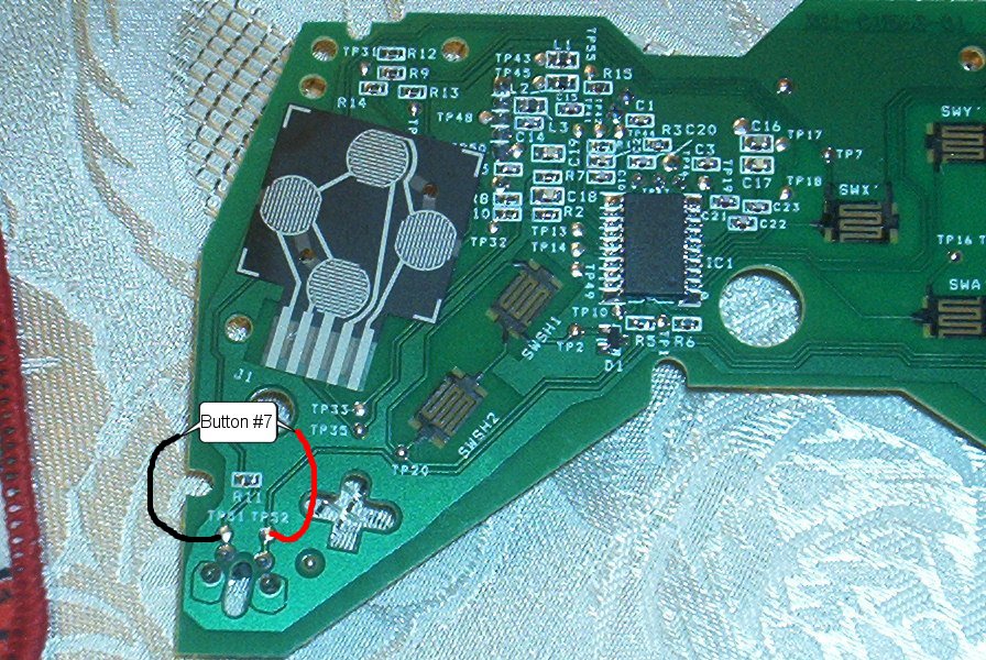
|
| Click for larger image. |
| Button 8 Wiring |
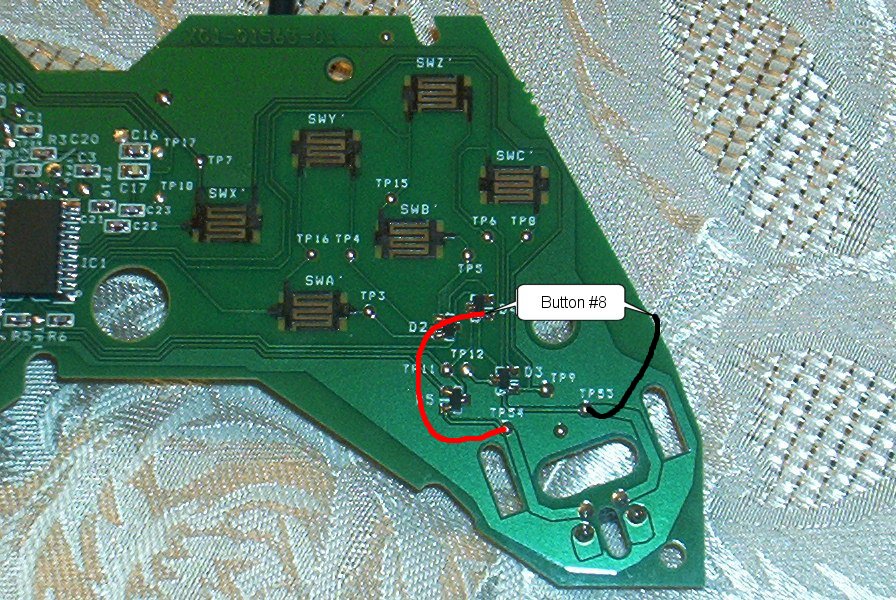
|
| Click for larger image! |
| Button 9 Wiring |
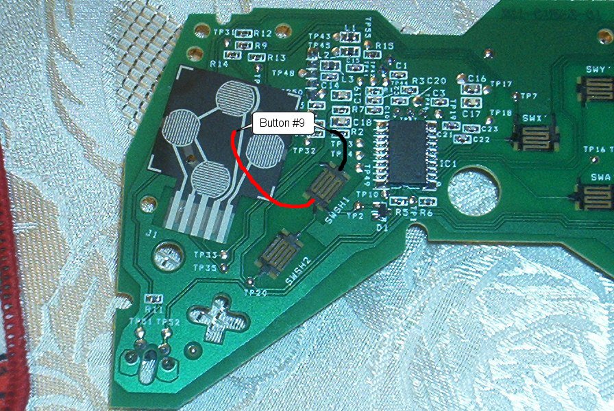
|
| Click for larger image! |
*Note: Make sure buttons work properly before sodering anything!!!
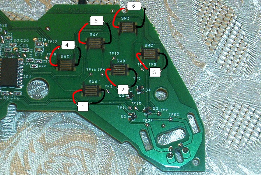
The next thing we will be connecting is the right side of the PCB. Buttons 1,2,3,4,5,6. Pay close attention to the sodering points in the pictures. You need to attach the wires on the black tabs that are on each side of the squares.
Once again make sure all of you connections are correct before sodering anything!!!
| Buttons 1,2,3,4,5,6 Wiring |
|
| Click for larger image! |
Well there is the basics to wiring a Sidewinder to arcade controls. I am by no means an expert on any of this stuff but am more than willing to help those in need. If you have any further questions feel free to contact me thru my contact page. Good Luck!!!
|